Yes. A professional injection molding supplier can work on mold design before steel is cut, covering wall thickness, draft, gates, runners, cooling, venting, ejection, parting lines, cavity layout, shrinkage allowance, and machine compatibility. Material data alone shows why supplier input matters: BASF lists 1.30% parallel and 1.40% normal molding shrinkage for one unreinforced PA6 grade, while a 35% glass-fiber PA6 grade is listed at 0.25% and 0.75%. A mold built around the wrong shrinkage or flow assumptions can produce dimensional errors even when the CAD geometry is correct, so mold engineering should start before final tooling release.
A supplier normally begins by reviewing the 3D model together with the resin grade, drawing tolerances, annual volume, cosmetic surfaces, assembly conditions, and expected molding machine. The review is not limited to whether the cavity can be machined. Engineers also check whether molten resin can fill the geometry at a practical pressure, whether the part can cool evenly, and whether it can leave the mold without distortion. ISO 20457:2018 provides a formal framework for tolerances on molded plastic parts and was confirmed as current in 2024. That tolerance review then leads naturally into part geometry.
Wall thickness is usually one of the first geometry items checked because a thick section cools more slowly than a nearby thin section. A designer may create a 5 mm solid boss to gain stiffness, while the surrounding wall is only 2 mm; the thicker mass can stay hot after the skin has solidified, raising the chance of sink, internal voids, and local dimensional change. A supplier may replace part of that mass with ribs or a cored boss, keeping the functional geometry while reducing unnecessary material. Material shrinkage data makes the scale easier to see: a nominal 100 mm feature at 1.4% molding shrinkage represents about 1.4 mm of dimensional change before mold compensation is applied. Once wall sections are reasonable, draft and ejection can be assessed more accurately.
Draft affects both surface quality and ejection force. A deep vertical wall with little or no draft can grip the core as the polymer contracts, especially on textured surfaces or materials with relatively high shrinkage. Adding draft during CAD development normally requires a small geometry change; correcting the same issue after mold trials may require re-machining cavity steel and checking mating surfaces again. The resin cannot be treated as a generic “plastic” during this work. BASF reports 1.30–1.40% molding shrinkage for Ultramid B3Z2 PA6, while its 35% glass-fiber-reinforced B3WG7 grade is listed at 0.25% parallel to flow and 0.75% normal to flow. That directional difference also affects gate planning.
| Mold-design item | Engineering question | Production effect |
|---|---|---|
| Wall section | Are thick-to-thin transitions gradual? | Sink, cooling time, dimensional consistency |
| Draft | Can the part release without excessive friction? | Ejector marks, scuffing, deformation |
| Gate | Where should melt enter the cavity? | Fill pressure, weld lines, packing |
| Cooling | Are high-temperature areas cooled evenly? | Cycle time, warpage, dimensions |
| Venting | Can displaced air leave the cavity? | Burns, incomplete filling |
| Ejection | Is force spread over suitable surfaces? | Part damage, automatic removal |
| Cavity count | Can the machine supply the required shot and clamp capacity? | Parts per cycle, mold size, unit cost |
Gate size and position have a strong effect on how pressure reaches the part during filling and packing. Guidance cited from DuPont notes that minimum gate dimension should generally be at least half of part thickness, while thin-wall parts may need a proportionally larger gate. A gate that freezes too early stops effective packing even when the machine can generate more pressure. A gate placed near a cosmetic face may also leave an unacceptable vestige, while a poor location around holes can place weld lines in mechanically sensitive areas. After the gate is located, runner balance becomes the next check in multi-cavity tooling.
A four-cavity mold should not simply contain four identical cavities connected by convenient channels. Runner length and pressure loss need to be balanced so all four cavities reach comparable filling and packing conditions. If one cavity fills earlier, it may receive more packing while another remains under-packed, producing cavity-to-cavity differences. Hot runners can reduce solidified runner material, while cold runners are mechanically simpler and may suit lower-volume work. The financial difference depends on shot size and production volume: if a cold runner adds 8 g of material to a 32 g four-part shot, runner material represents 20% of total shot weight before any permitted regrind is considered. Runner selection therefore leads directly to cooling and cycle calculations.
Cooling often occupies a large share of the molding cycle because the part must become stiff enough to eject without unacceptable distortion. Water channels have to reach areas around cores, ribs, bosses, and thick sections while leaving enough steel for strength. Delrin’s molding guidance recommends mold temperatures of 80–100°C for standard grades and notes that temperatures up to 120°C may be used for high-precision parts, showing why one cooling setting cannot be applied to every resin and geometry. Cooling uniformity also matters because poor mold-temperature uniformity is listed as a cause of part distortion in Delrin processing guidance. Once temperature control is mapped, cycle-time economics can be estimated.
Consider a four-cavity tool producing 1,000,000 parts. It requires 250,000 successful cycles before scrap and downtime are added. At a 30-second cycle, theoretical molding time is about 2,083 hours; at 27 seconds, it falls to 1,875 hours, a difference of roughly 208 machine hours, or 10%. The example does not claim every cooling redesign can remove 3 seconds, but it shows why channel placement deserves engineering work before machining. A few seconds per cycle can represent hundreds of machine hours at production volume. Faster cooling still has to preserve part dimensions, which brings packing and shrinkage back into the mold design.
Packing pressure cannot correct every geometry problem. Delrin’s molding guide gives a recommended hold-pressure range of 60–110 MPa depending on grade and provides a general hold-time guideline of 8 seconds per millimeter of part thickness, based on a 3 mm part. The same guide explains that high mold temperatures and thick sections can increase shrinkage. A supplier can use pressure studies during mold trials to identify when the gate freezes and whether more hold time still changes part weight. If part weight stops increasing, extending hold time further mainly adds cycle time. That processing work depends on venting being designed correctly as well.
Air occupying the cavity must leave as molten polymer advances. Poor venting can contribute to incomplete filling or overheated trapped gas near the end of flow, particularly around ribs, thin sections, and areas where separate flow fronts meet. Vent locations can be planned at the parting line, around ejector features, or through purpose-built inserts when geometry requires it. Vent dimensions depend on the resin because a vent that is safe for a viscous material may allow flash with a lower-viscosity grade. A supplier therefore needs the exact material designation, not merely “ABS,” “PA,” or “POM.” BASF data alone shows PA6 grades with molding shrinkage ranging from about 0.25% to 1.40% depending on reinforcement and direction. Material definition then supports a realistic tolerance review.
Very tight dimensions should be reserved for features that actually need them. Plastic dimensions can change with mold temperature, packing, fiber orientation, moisture condition, and post-mold thermal history, so applying machining-style tolerances across an entire plastic housing can make the tool harder to qualify without improving assembly. ISO 20457:2018 covers manufacturing tolerances for molded plastic parts and allows additional specifications where functional requirements require them. A supplier can separate fit dimensions from cosmetic or non-mating dimensions, then use replaceable inserts around dimensions that may need adjustment after first-off samples. That approach also makes tool correction more controlled after measurement.
Ejection is reviewed at the same stage because the part normally shrinks around core features during cooling. Ejector pins placed on thin unsupported walls can leave marks or deform the part, while too few ejectors concentrate force in small areas. Sleeves can work around cylindrical bosses, stripper plates can distribute force around larger edges, and lifters can combine ejection with undercut release. The supplier also checks whether an undercut can be removed from the product geometry before adding a slider or lifter. Eliminating one moving mechanism can remove components that otherwise need fitting, lubrication, sensing, and maintenance through a production program that may exceed 1,000,000 parts.
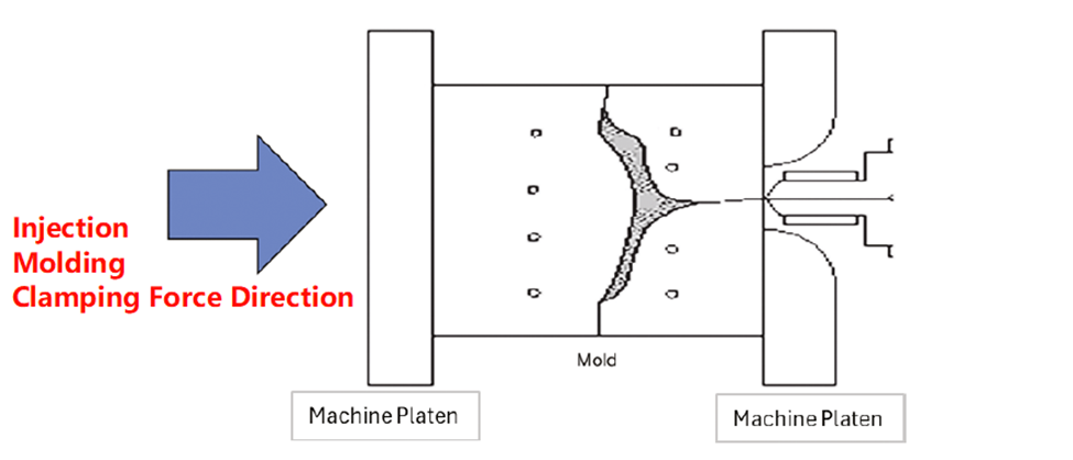
Cavity count is then matched to demand and machine capacity rather than increased automatically. Moving from one cavity to four cavities can theoretically multiply parts per cycle by 4, but the mold becomes larger, runner balance becomes more demanding, cooling circuits multiply, and the molding machine must provide enough shot capacity and clamp area. At 20 g per part, four cavities require 80 g of finished-part material per cycle before runners are included. At 16 cavities, the same part requires 320 g before runners. A supplier should therefore quote the molding machine, cavity layout, runner type, expected cycle, and estimated annual hours together rather than quoting mold steel as an isolated item.
The same review is useful when sourcing internationally. A buyer comparing a Plastic injection molding supplier China option with suppliers in Europe, Mexico, or the United States can request the same engineering package from every bidder: DFM comments, proposed mold material, cavity count, runner design, gate position, cooling layout, expected cycle range, machine size, inspection plan, spare-component list, and drawing standard. A quote that is 15% lower at tooling purchase can become more expensive over 500,000 or 1,000,000 parts if cycle time, scrap, maintenance hours, or manual handling are higher.
Before approving tool manufacture, the buyer can also request a mold-design review using the actual 3D mold assembly rather than a quotation sketch. The review can cover parting lines, shutoffs, slides, lifters, inserts, cooling connections, ejector access, replaceable wear areas, and sensor locations. Changes made before steel machining are generally easier to control than changes discovered during molding trials. The purchase specification should also state who owns the mold data, which CAD format will be supplied, which components follow recognized standards, and what dimensional report is required after sampling.
First samples should then be treated as measured engineering output rather than proof that the mold “works.” A useful trial records melt temperature, mold temperature, fill time, peak pressure, hold pressure, hold time, cooling time, cycle time, cavity identification, and part weight. For a four-cavity mold, measurements should remain traceable to cavities 1–4 so one cavity does not disappear inside an average. A 1% average dimensional deviation can look acceptable while one cavity consistently sits outside tolerance. Cavity-level data gives the supplier enough information to adjust steel, cooling, venting, or processing before the mold enters repeated production.